Optical Phase Demodulators
Optical Interleavers
 
Standard Optical Interleaver
Asymmetric Optical Interleaver
Switchable Interleaver
Co-Packaged Interleaver
Multi-Staged Optical Interleaver
"Super"-Wide Passband Interleaver
O-Band Interleaver for 5G-PON Mux/DeMux
   
Tunable Optical Filters
Optical Monitors
Integrated High-Speed Receivers
Optical Test & Measurement
Optical Spectrum Analyzers
Lasers and Light Source
F-P Etalons Products
Custom-Design Products
Home > Products > Optical Interleavers > Standard Optical Interleaver
Standard Optical Interleaver  
 
Optoplex Compact Optical Interleaver Device
Optoplex Optical Interleaver Module
   
Optical Interleaver PDF Datasheet
White Papers - Interleaver spectra
  • Description
  • Features
  • Applications
  • Typical Performance
  • Parameter Definition
Product Description - Optical Interleaver

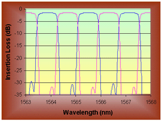
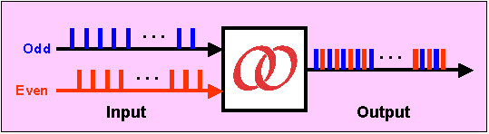
An innovative technique for expanding the number of channels per fiber involves an optical device, called an optical interleaver. For example, in most DWDM equipment, the standard channel spacing is 100 GHz. But spacing the signal-carrying frequencies every 50 or even 25 GHz can double or even quadruple the number of channels per fiber. This job is accomplished by an optical interleaver. Such a device takes two multiplexed signals with 100-GHz spacing and interleaves them, creating a DWDM signal with channels spaced 50 GHz apart. The process can be repeated, creating even denser composite signals with 25-GHz or 12.5-GHz spacing. The signals at the receiving end are recovered with the same devices used as splitters or optical de-interleavers. Thus, devices and/or networks can be upgraded without requiring that all devices be upgraded, or network bandwidth can be increased.

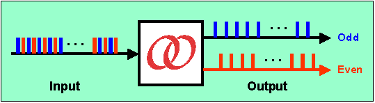
Optoplex's Optical Interleaver products are based on patented Step-Phase Interferometer design. Used as a Demux (or Mux) device, an optical interleaver separates (or combines) the odd and even channel signals (see the schematic diagram below). Each optical interleaver device is optimized to cover either C- or L-band wavelengths, with the option of covering C+L band. The current standard optical interleaver product family supports 100-200, 50-100, 25-50, and 12.5-25 GHz channel spacing, covering up to 90, 180, 360, and 720 channels, respectively, as well as other custom spacings in that range, such as 33.33-66.66 GHz. Dual-stage optical interleavers are also available.

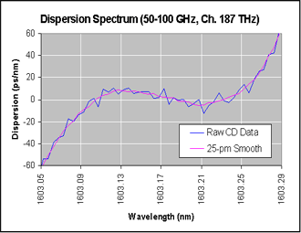
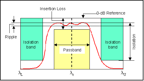
Optoplex's Optical Interleavers have wide and flat passband, low (and customizable) dispersion, low and uniform insertion loss, low PDL, high channel isolation and very low thermal drift.

For Uneven or Asymmetric Optical Interleaver, please visit a different page.

Symmetric Optical Interleaver
Optoplex interleaver
Symmetric Optical De-Interleaver
Optoplex de-interleaver
Features and Benefits of Optical Interleaver
  • Wide and Flat Passband
  • Minimal PDL
  • High Channel Isolation
  • Minimal Thermal Drift
  • Low and Customizable Dispersion
  • Low Insertion Loss & IL Uniformity
  • Dual C- and L-Band Coverage
  • Super-Band Version Available
  • Bi-Directional Mux/DeMux Co-packaged Interleaver Available
  • Customized Channel Spacing, such as 33.33-66.66 GHz
  • Asymmetric/Uneven Optical Interleaver Available
  • Tunable Interleaver Available
  • Telcordia GR-1221/63 Qualified
Applications of Optical Interleaver
  • Extend Existing Network Capacity
  • Bridge Existing & New DWDM Platforms
  • System Upgrade
  • Bi-Directional Networks
  • Total Signal Power Detection for Raman Amplifier
  • Multi-Wavelength Transponder
  • Flat-top Comb Filter
Typical Performance of Optical Interleaver
Spectrum of Optoplex super interlleaver Dispersion of Optoplex interleaver
Parameter Definition of Optical Interleaver

Parameter Definition

 Example

Wavelength Range (nm) is the spectral range over which the optical interleaver's optical performance can be met.

1530.33 - 1563.05 nm

Insertion Loss (dB) is the relative power level transmitted to the output ports referenced to the 0-dB level when the optical interleaver is inserted. It is the power difference between the 0-dB level and the minimum power level measured within a given passband window. See figure below.

1.5 dB

Ripple (dB) is defined as the power difference between the minimum loss and the maximum loss within a given passband.

0.3 dB

Passband Bandwidth (GHz) is defined as the spectral width centered at ITU grid at a given power level, typically at 0.5 dB below the minimum insertion loss point.

ITU ± 30 GHz

Isolation (dB) is defined as the power difference between maximum insertion loss measured within a given passband window and the minimum insertion loss measured within the adjacent stopband window

24 dB

Parameter definition of Optoplex interleaver


Insertion Loss Uniformity (dB) is the difference between the maximum insertion loss and minimum insertion loss over all channels, either within one output port or both ports.

0.3 dB

Polarization Dependent Loss (PDL) (dB) is the difference between the maximum and minimum insertion loss over all polarization states within a given passband window.

0.3 dB

Chromatic Dispersion (CD) (ps/nm) is the derivative of the Group Delay versus wavelength within a given passband width.

24 ps/nm within ITU±20%FSR

Polarization Mode Dispersion (PMD) (ps) is the maximum Differential Group Delay within a given passband width.

0.2 ps within ITU±30%FSR

Optical Return Loss (dB) is the ratio between the input power and the reflected power over all polarization states at each port , RL = -10×log10(Pr/Pin).

40 dB

Operating Temperature (°C) is the ambient temperature range over which the device's performance spec can be met.

-5 to 65 °C

Storage Temperature (°C) is the ambient temperature range over which the device can be stored without affecting its intended application afterwards.

-40 to 85 °C

Product Request and Ordering Information
Please speak to Optoplex Sales persons. If you request custom-designed optical interleaver product, please provide the following parameters:
  • Wavelength range
  • Input and output channel spacings
  • Pass bandwidths
  • Fiber length
  • Optical connector type